Home › Forums › Bug Reports › ac power source port impedance 75Ω
- This topic has 8 replies, 2 voices, and was last updated 1 year, 4 months ago by
t_chiba.
-
AuthorPosts
-
16. December 2022 at 10:28 #6910
Hallo
S-parameter analysis.
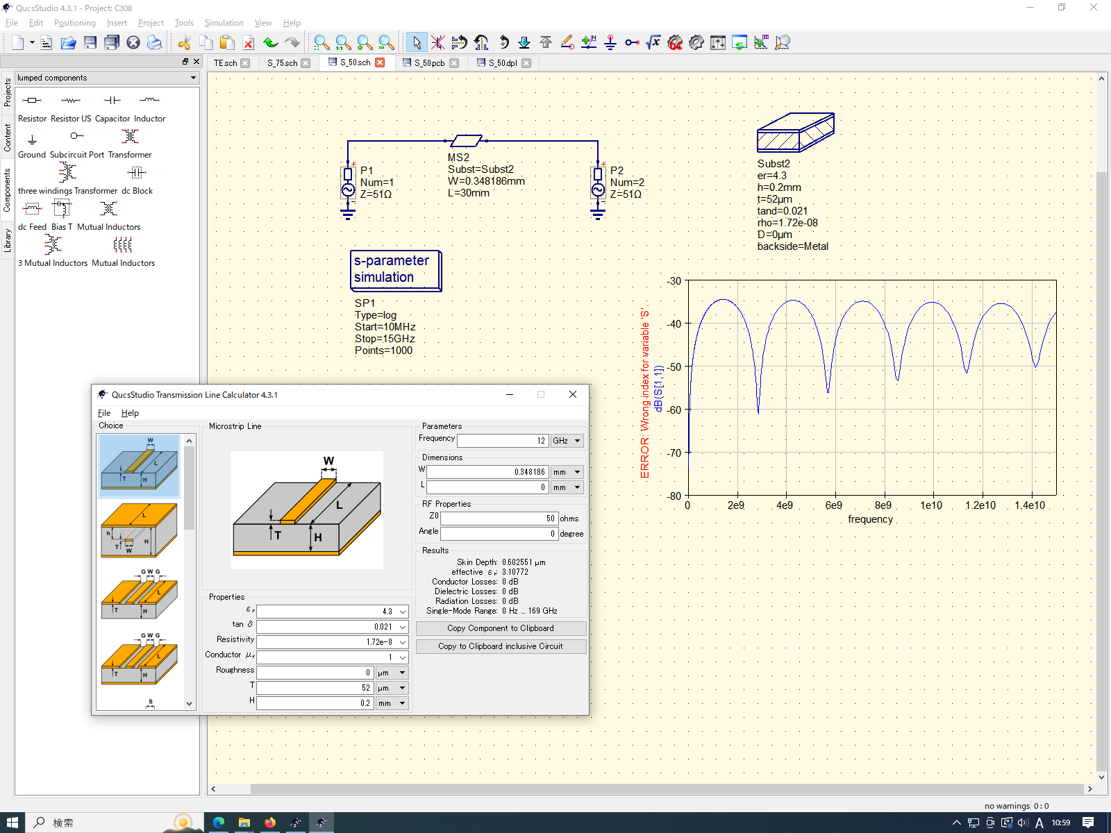
Set the port impedance of the ac power source to 75Ω.
Incorrect result.Because it was different compared to SONNET.
Also theoretically incorrect.The port impedance of 50Ω was consistent with SONNET.
Is there a bug when changing the port impedance?
16. December 2022 at 16:08 #6911Hi t_chiba,
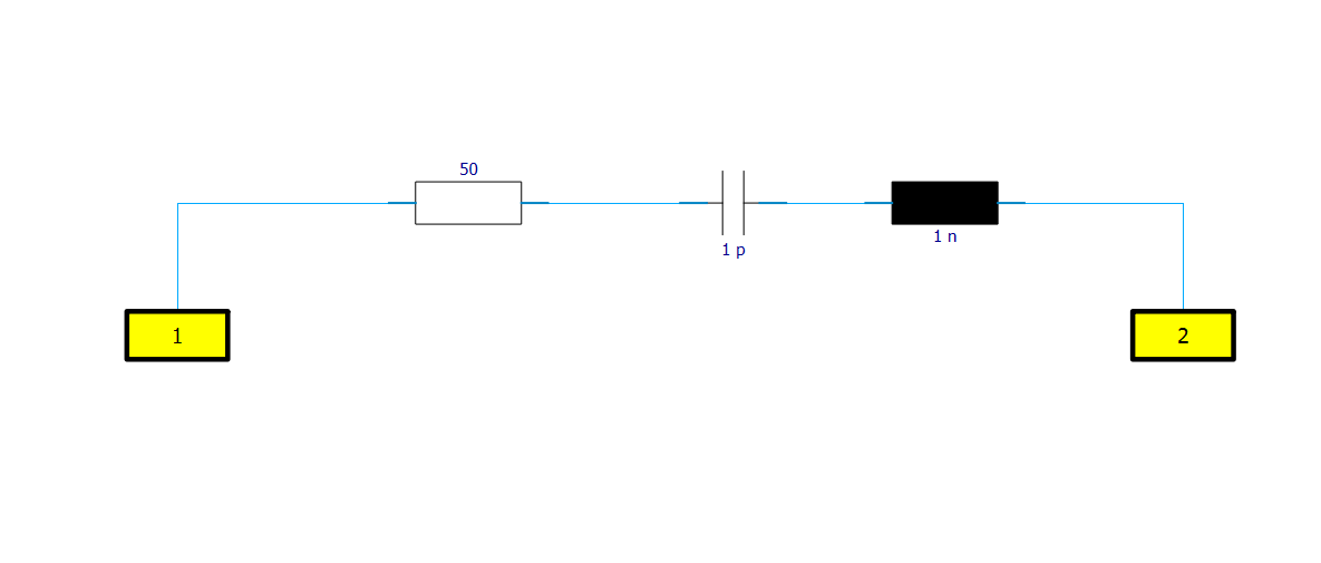
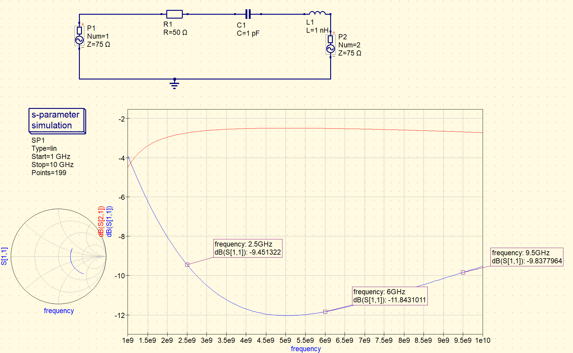
could you share a schematic or qucs project file, please?
I did a quick comparison between qs and Dassault cst. Seems ok for me. See attached files.
Also, there is only “AC Voltage source”, “AC current source” and “power source”
Cheers
Carsten
19. December 2022 at 0:31 #6930Hello carsten
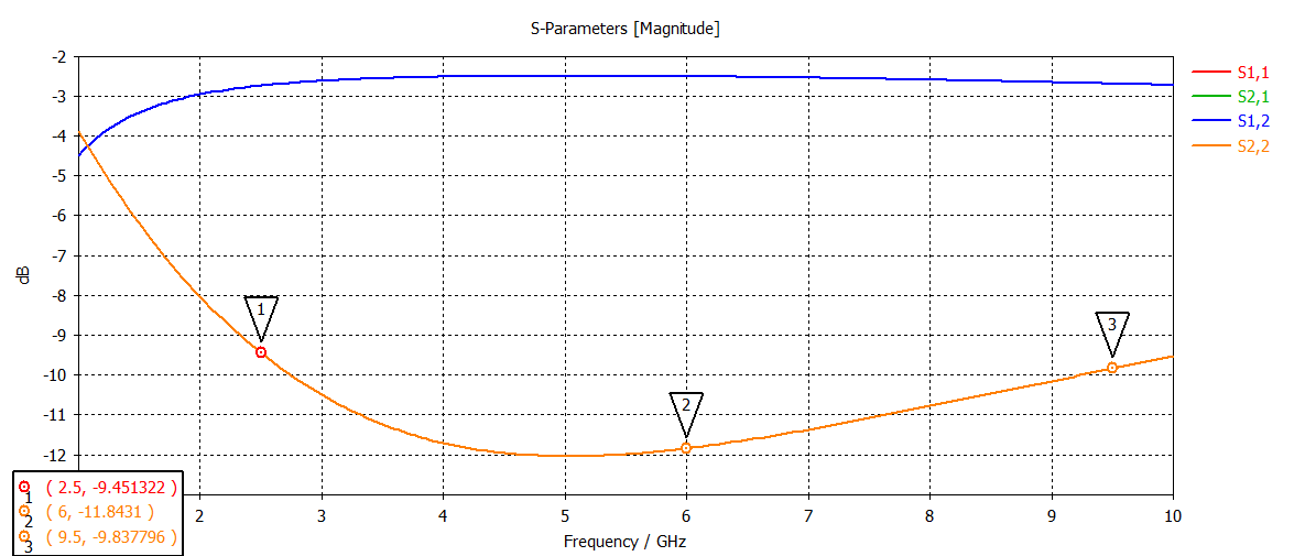
sch and waveform.
75 ohm is disturbed around 12 GHz.
<div style=”width: 0px; height: 0px; overflow: visible; position: static;”></div>Attachments:
19. December 2022 at 17:11 #6936CST agrees more or less w/ qucs.
maybe sonnet ist buggy 🙂 ?
20. December 2022 at 6:13 #6947Thank you.
I see the same results for QUCSSTUDIO and CST.
However, I do not know if it is a bug in SONNET.
I had a friend analyze it with Hyperlynx and it was the same as SONNET.When port impedance and line impedance match.
Is it correct behavior that the waveform is corrupted?
<div style=”width: 0px; height: 0px; overflow: visible; position: static;”></div>20. December 2022 at 20:32 #6952> When port impedance and line impedance match.
This sentence makes no sense. Maybe your text is mis-formatted?I am curious: The differences seem marginal (on S11 levels of ~-70 dB). What kind of a circuit do you have where this is relevant?
Maybe its an effect of higher order modes in the microstrip: https://www.microwaves101.com/encyclopedias/microstrip
I think they should not be present with your freq/substrate spec, but maybe the onset of them is visible on these tiny power levels. And maybe the software packages use different models that include these modes or not.You could 3DEM-model it. Check the EM simulation examples on the qucsstudio website.
22. December 2022 at 6:07 #6959Thanks for the interesting web.
>Higher mode effects.
I don’t know much about it, but I think it is possible.For example.
When there are dk1 and df0
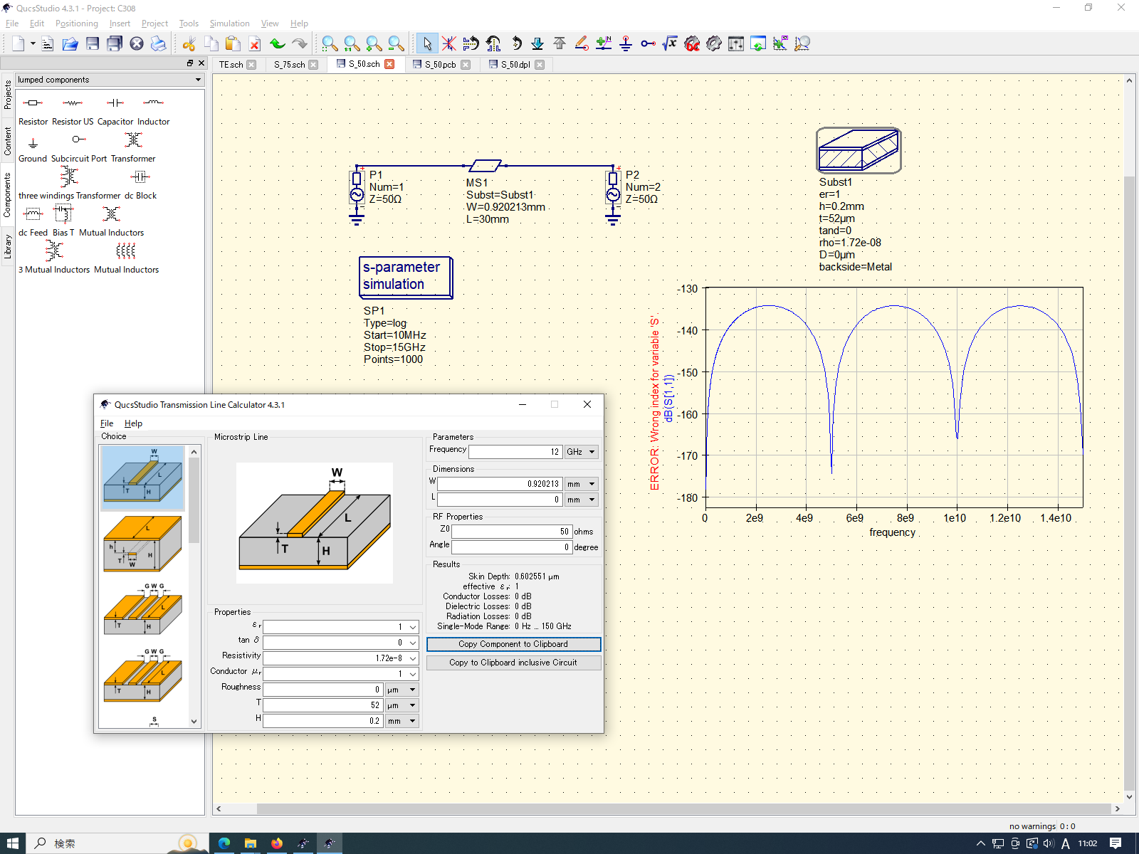
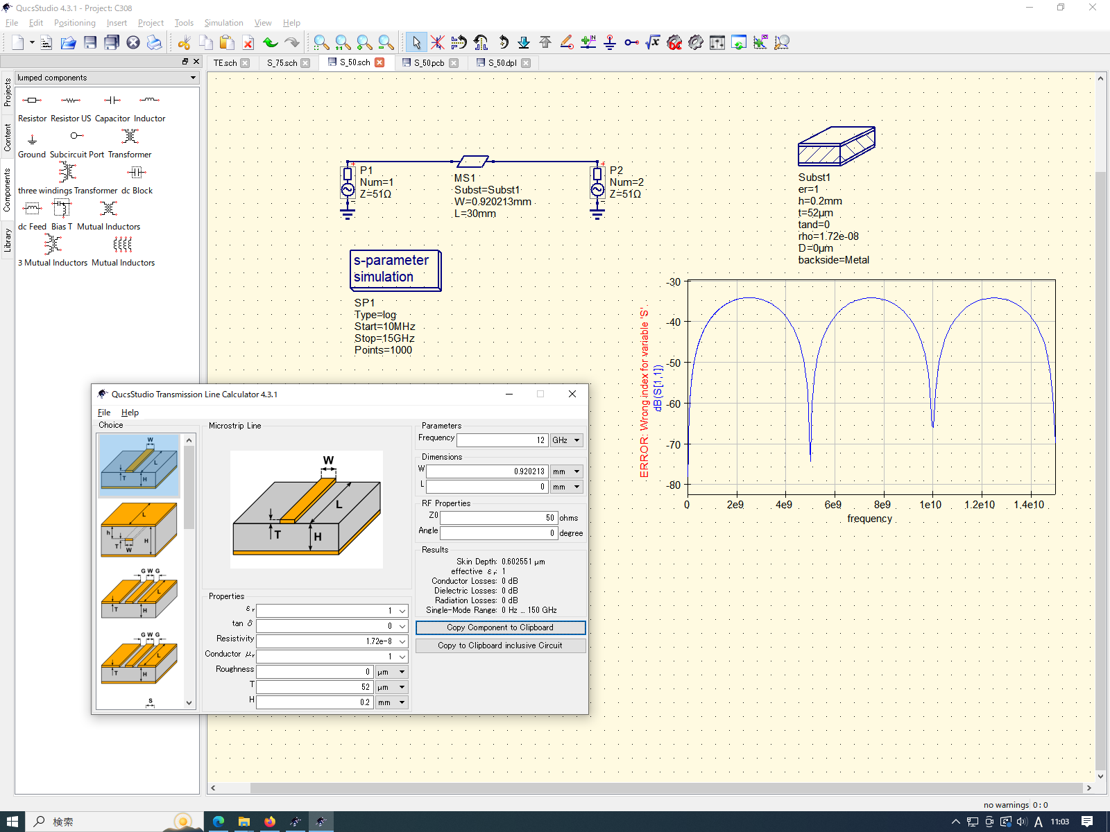
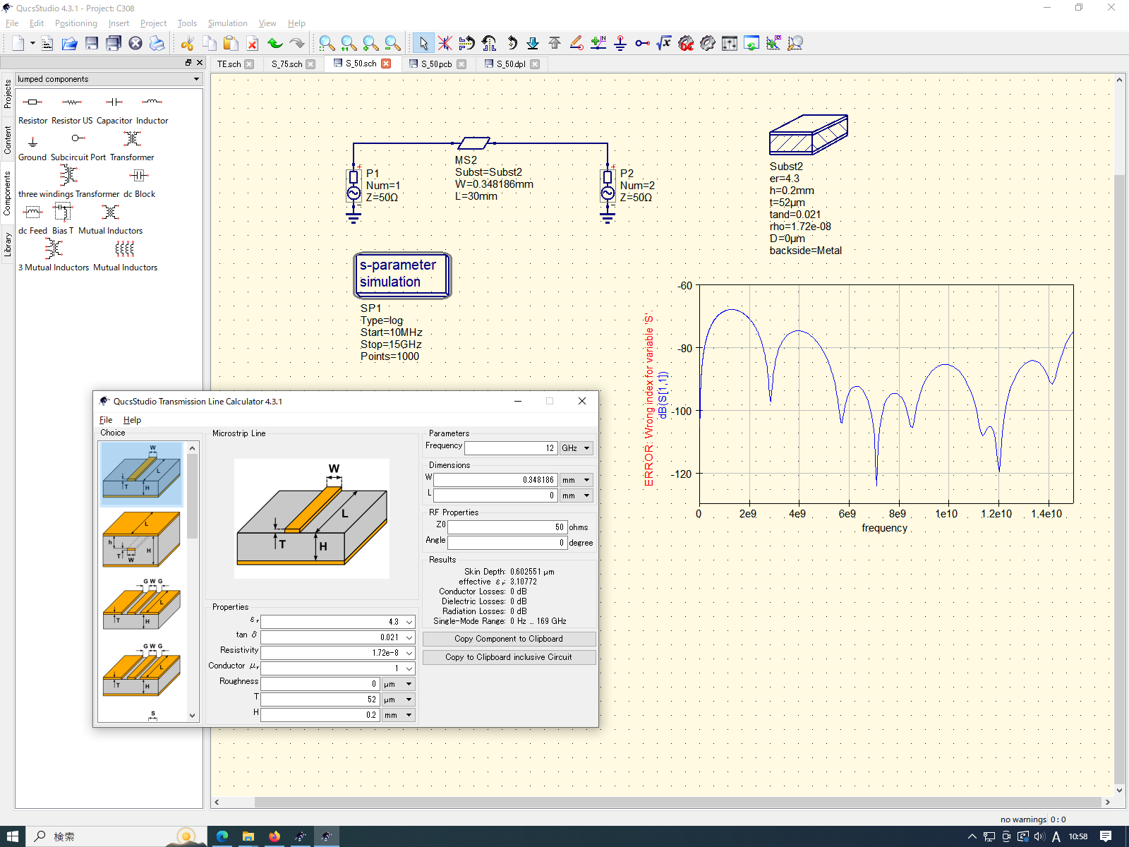
there is no difference between the waveforms of port50Ω/line50Ω and port51Ω/line51Ω.When dk4.3 and df0.021 (FR-4)
There is a difference in waveform shape between port50Ω/line50Ω and port51Ω/line51Ω.*What is noteworthy is not the value but the waveform.
When port impedance and line impedance match, the waveform is collapsed.
QUCSSTUDIO/CST has the same behavior.
SONNET/Hyperlynx behaves differently than QUCSSTUDIO/CST.I do not know what is the correct behavior, but can I assume that QUCSSTUDIO is correct?
<div style=”width: 0px; height: 0px; overflow: visible; position: static;”></div>22. December 2022 at 9:18 #6964>I do not know what is the correct behavior, but can I assume that QUCSSTUDIO is correct?
I don’t know. You could post this in one of these forums:
https://www.edaboard.com/#analog-design.10
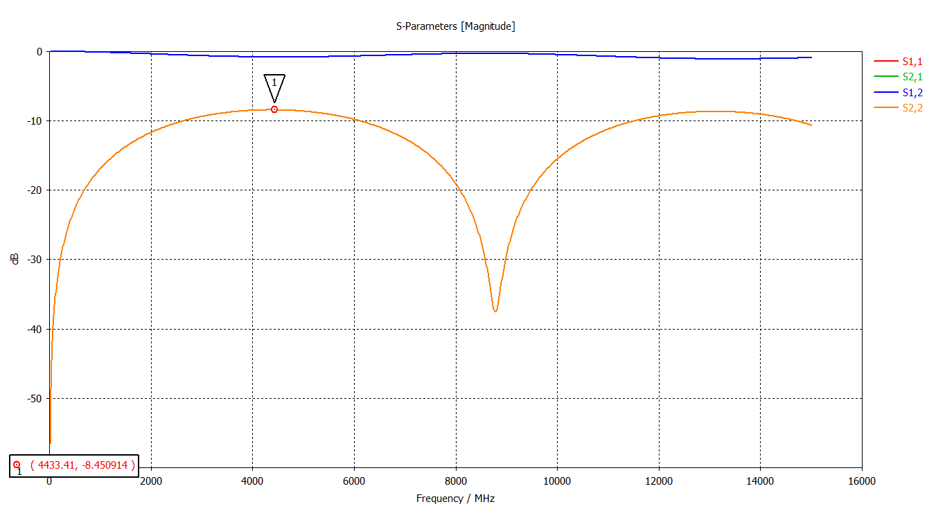
I asked an rf question some while ago and got some very knowledgeable answers.FYI The repetetive “dips”in the S11-shape – I think – originate from fractional reflections at discontinuities (e.g. change from port to microstrip). If the discontinuities are n * lambda/2 apart, they cancel each other out and you get a perfect match (very negative S11 value)
22. December 2022 at 10:25 #6965>https://www.edaboard.com/#analog-design.10
Very interesting.
Thank you for your response.
The simulator is useful but difficult.
I will continue to study it.
<div style=”width: 0px; height: 0px; overflow: visible; position: static;”></div> -
AuthorPosts

- You must be logged in to reply to this topic.