- This topic has 10 replies, 3 voices, and was last updated 3 years ago by
QucsStudio.
-
AuthorPosts
-
6. April 2021 at 6:08 #860
It seems the hybrid coupler is limited to 180deg but the model allows you to enter a different value. Why not allow 90deg?
7. April 2021 at 17:40 #862Additionally I cannot get Coupler or Hybrid to work properly. I can’t get a simple circuit power combining 2 of the Gain blocks with 2 Couplers or Hybrids to work properly.
They don’t work 100% in Qucs either. In the case of Qucs, ports are swapped in the Hybrid. I also get some odd data power combining 2 of the Gain blocks with the Coupler.
8. April 2021 at 11:46 #865Of course, you can simulate a coupler with the phase that you want. But as the warning explains, physically, the result makes sense with 180 degree only. This means that in reality, (ideal) devices with other phases does not exist.
8. April 2021 at 16:00 #867I sent a long winded email about this and included my test files.
I ‘m unsure how to use and phi in the ideal coupler. The default is k=0.7071 and phi=90. When I try to use phi=180, I cannot get any value of k to work.
In addition when testing the ideal coupler, loss and phase data are wrong for 3dB 90deg.
Attachments:
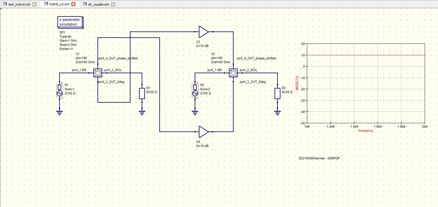
9. April 2021 at 0:15 #870I tried these, the hybrid, 2 x hybrid and coupler – had to play around with the ports of the hybrid but these (se attachment) seem to give reasonable results.
I have also used the coupler before with reasonable results (90 deg phase shift)
73 – Hannes – SM6PGP
9. April 2021 at 0:38 #874The data for coupled_lines_cpl seems wrong. The phase (S41) is 7.05e-31. The phase difference between the two outputs ports should be 90 deg. Am I to assume 7.05e-31 means 0?
9. April 2021 at 17:53 #875SM6PGP
Michael says the 7.05e-31 is “0”. It seems any small number is considered as a “0”. 90 or 180 get calculated as whole numbers however.
It seems the “ideal” Hybrid is not a “symmetrical” model. There is only one port that can be used as the Input or Sum. I can only get your data if I place the Hybrid as shown in your schematic. It would be useful to identify this port on the schematic symbol. I assume this is why you had problems making your amplifier to work.
Attached is two alternate schematics using Hybrid 90/180 where the data is wrong.
Attachments:
9. April 2021 at 17:54 #877Hybrid 180
Attachments:
9. April 2021 at 23:00 #879I consider all small numbers as zero, and large negative dB-values as “no power”
Yes, it would be good to have a small mark on the symbol to identify input/sum port. It is always good to check that you get reasonable values.
73 – Hannes – SM6PGP
11. April 2021 at 2:00 #884The manual shows the Hybrid’s ports 1-4. The schematic symbol has no numbering. Port 4 is the In/Sum port.
Attachments:
12. April 2021 at 10:01 #887The ports of the hybrid are marked correctly in the schematic: A small “phi” between the ports with the phase shift and zeros between the ports without phase shift.
Furthermore, there are no input or output ports. The device is passive and all ports are bi-directional.
All results I’ve seen so far are correct, too! So I really cannot understand why some people are spreading around reports that claim something different. Indeed, this kills the project!
-
AuthorPosts


- You must be logged in to reply to this topic.