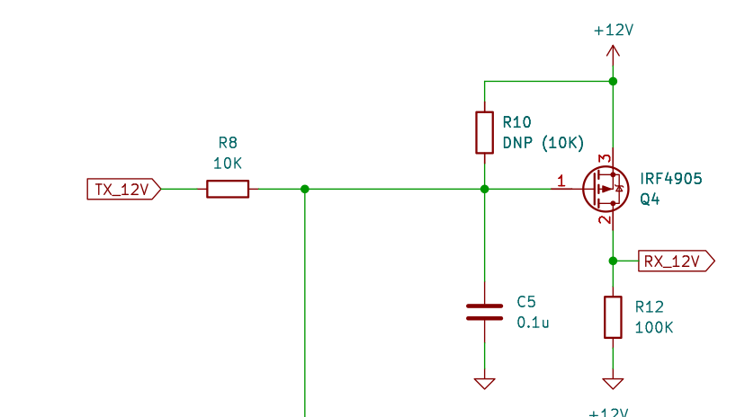
Please have a look at below schematic. I have built it in real life, and the result is what is expected. Low at the input gives +12V at label RX_12V. High at the input gives 0V at label RX_12V.
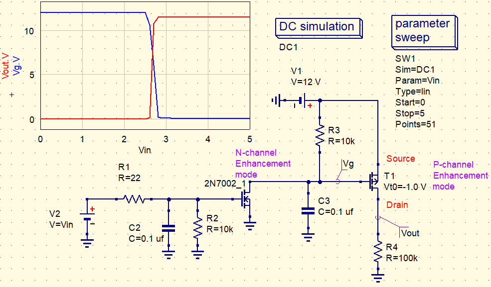
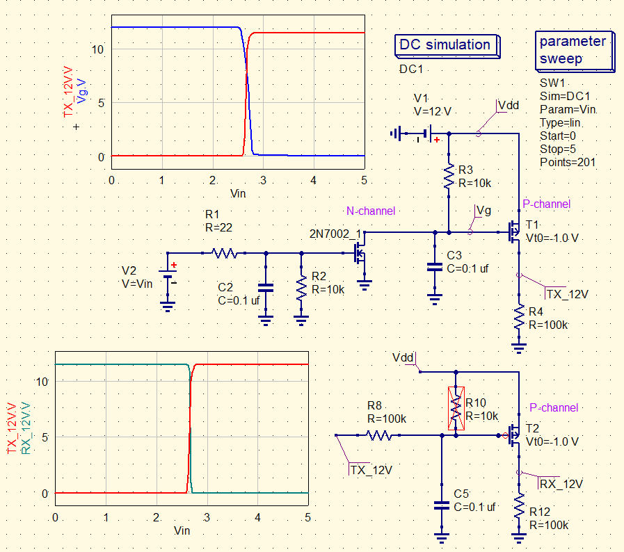
However, when I try to simulate the circuit I do not see the expected output. The output stays at around +12V no matter what the input is.
Can anyone please tell me how I should do a DC simulation for this schematic ?

I have tried a transient simulation with a pulse voltage source (from 0 to 3.3v, pulse length 1 second, rise and fall 1 nanosecond) which gives me a fairly constant output of +12V at RX_12V.
A DC simulation does not give me any output in the graphics at all…..
.