Home Forums Bug Reports Frequency domain incorrect netlist interpretation/simulation.

Viewing 8 posts - 1 through 8 (of 8 total)
  • Author
    Posts
  • #9108
    Andy_JP
    Participant

      Absolutely equivalent networks are simuated differently depending on the shunt connections.


      For simulating a matching network I use temporary shunts. And very weird results are coming from simulations. See the image attached.

      Attachments:
      #9110
      Andy_JP
      Participant

        Version 5.8

        #9111
        Carsten
        Participant

          usimmics does not support complex source impedances yet. Does the effect disappear if the source impedances are real?

          #9112
          Andy_JP
          Participant

            Carsteen. For longer than 2 years it was told exactly contrary – it should support, though it is not well documented, since the latest QucksStudio.

            I think there even was a discussion on this forum.

            There are many badly documented things like Touchstone imedance conversion matrix…. which does not work correctly btw, while the devs claim it should do the thing.

            #9113
            Andy_JP
            Participant

              Regardless of supported or not – the BUGREPORT is about different thing –

              incorrect handling of the netlist

              #9114
              Andy_JP
              Participant

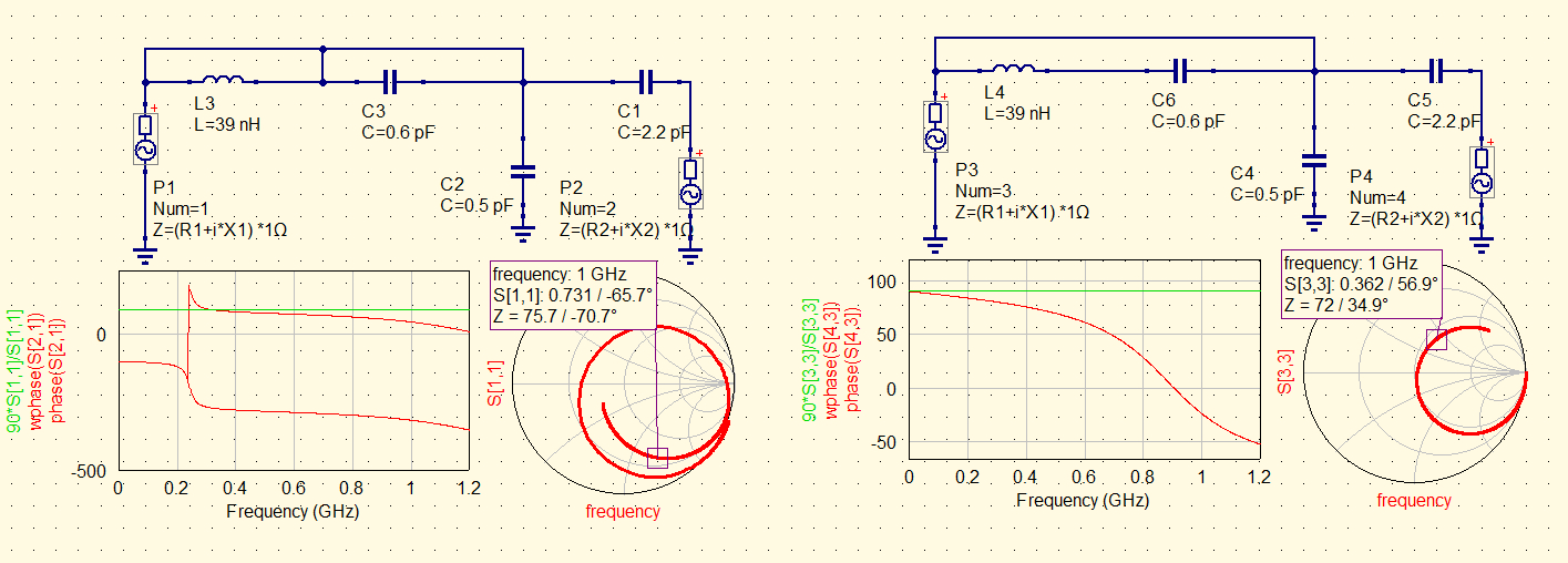
                See the circuit – all the shunt network is the same node – zero impedance. It should not give different results regardless of connecting the middle point.

                #9115
                Andy_JP
                Participant

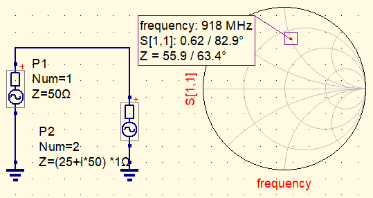
                  Carsteen, to be clear: Port complex impedance is supported. But the SMITH tool does not support arbitrary reference impedance (Zo), only 50Ω. So it should be renormalized manually. And I have no idea how to do that, if there is any function for that.

                  Attachments:
                  #9125
                  Carsten
                  Participant

                    A simplified example:

                    The inductor on the left is interpreted as being parallel to R1

                    The netlist generated for the left circuit alone seems ok:

                    R:R1 gnd _net0 “50 Ω” “26.85” “european” “SMD0603”
                    L:L1 _net0 _net0 “39 nH” “0” “” “inductor_1mH”
                    .SP:SP1 “lin” “0.01 GHz” “1.2 GHz” “100” “no” “1” “2” “none”
                    Pac:P4 _net0 gnd “1” “50 Ω” “0 dBm” “1 GHz” “26.85” “con_2”

                    I don’t like that.

                  Viewing 8 posts - 1 through 8 (of 8 total)
                  • You must be logged in to reply to this topic.