Home › Forums › Bug Reports › Regarding GTUMAX computed value vs handcalculated value
Tagged: Active RF circuits, max_ulgain_dB
- This topic has 2 replies, 2 voices, and was last updated 4 days, 19 hours ago by
hptrivedi95.
-
AuthorPosts
-
3. March 2026 at 5:46 #9224
Hi QucsStudio community,
I am Het Pranav Trivedi, an enthusiastic RF Engineer. I have been working with QucsStudio (u-Simmics-5.8) for the past 2 months.
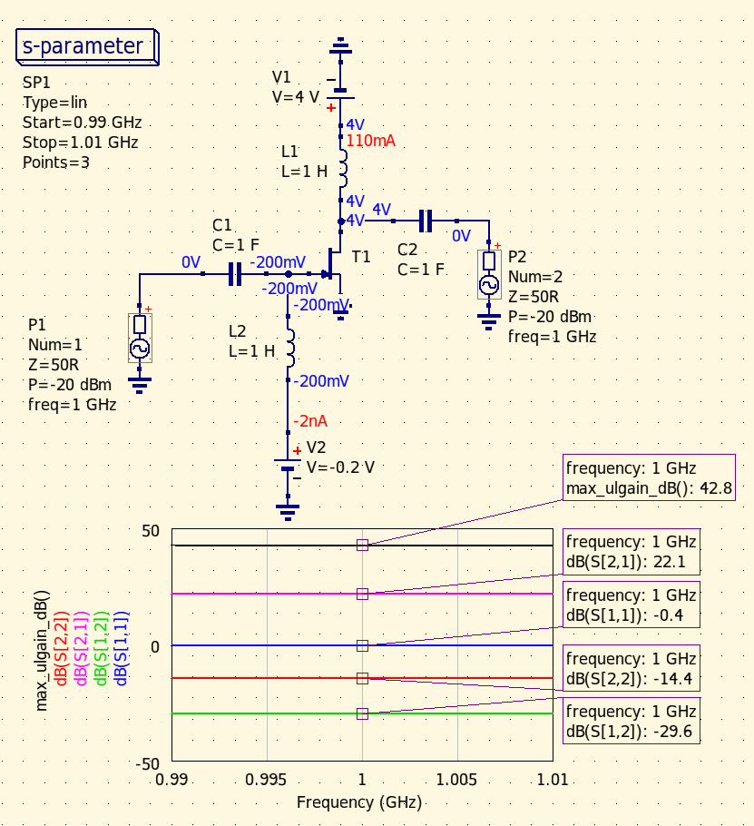
Recently, while simulating a circuit, I found that it yielded a max_ulgain_dB of 42.8 dB, which, to the best of my understanding, indicates the maximum unilateral transducer gain. When I hand calculate it using S-parameters, I get 32.8 dB gain. I am attaching an image of the circuit and an image of the .s2p file. The transistor used is from a special transistor library>>atf3413 low noise pHEMT
The formula I use for hand-calculation is as follows:
GTU,MAX = GAU,MAX = GPU,MAX = [(1/(1 – |ГS|^2))]*[|S21|^2]*[(1/(1 – |ГL|^2))] (This formula is referenced from – Microwave Transistor Amplifier Analysis Design, 2nd Edition by Guillermo Gonzalez )GTU,MAX dB = 10log10(GTU,MAX)
S12 = 0 is assumed for GTU and then ГS = S11*, ГL = S22* gives the GTUMAX as to my understanding. This way it only depends on S – parameters and not on source and load impedances, as they are assumed to be conjugate as described above. So, |ГS| = |S11*| = |S11| , |ГL| = |S22*| = |S22| in the above formula.
GLUMAX = 0.16 dB, GSUMAX = 10.438 dB , GD = 22.064 dB
GTUMAX = 10.438 + 22.064 + 0.16 = 32.662 dB
Now, agreeably at 1 GHz, K < 1 and Δ < 1, along with |S12| ≠ 0 or < 0.005 (Considering |S21| < 40), thus unilateral gain merit cannot be applied here, although, as I understand it can still be computed assuming |S12| = 0. GMSG hand calculation aligns well with max_gain_dB.
Kindly help me figure out what I am missing.
PFA
Best Regards
Het (KJ5BEI)3. March 2026 at 23:35 #9228Hello Het,
In the directory where uSimmics is installed there is a subdirectory named “doc” in which you find the file “technical.pdf”. This contains a detailed description of all calculations used in uSimmics. The calculation you are interested in is on page 38 under “4.6.2 Gain”. I am not sure if your own calculation is different.
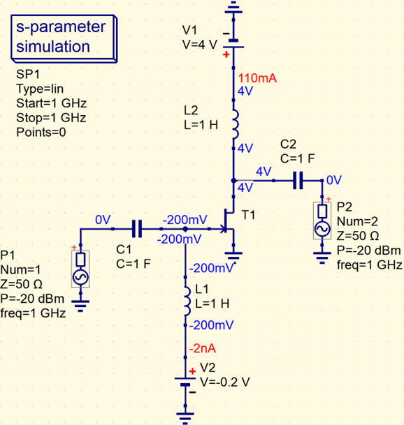
In a first step I recommend in this case not to use the s2p-file to get S-parameter values but to use a diagram to plot all parameters and set markers. Moreover, for doing hand calculations I suggest to use uSimmics itself. In a diagram you can plot a graph defined by your own equation and add a second graph with the max_ulgain_dB(S) function for comparison. That makes it easy to check if your own formula is different from the one used by uSimmics. I did not define an equation in the attached simulation but you certainly get the idea.Regards
Max
Attachments:
4. March 2026 at 12:52 #9230Hi Max,
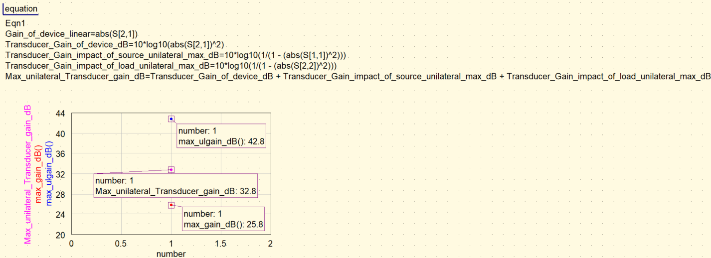
Please view the attached image, which reports the maximum unilateral transducer gain from equations computed in QucsStudio using S-parameters as 32.8 dB (equations are also visible). This is because the image of .s2p file I attached was extracted directly from the schematic. The formula given in the technical document reduces to the one that I mentioned in the previous post under the conditions of a unilateral maximum approach to gain. It is also mentioned in chapter – 3 page 230 of Microwave Transistor Amplifier Analysis Design, 2nd Edition by Guillermo Gonzalez.
I am where I started. However, thank you for your prompt response and debug suggestion.
PFA
Best Regards
Het (KJ5BEI)Attachments:
-
AuthorPosts

- You must be logged in to reply to this topic.