Forum Replies Created
-
AuthorPosts
-
8. October 2025 at 10:04 in reply to: uSimmics 5.8 crashes when selecting Remove within Parameter Tuning #9118
I confirm.
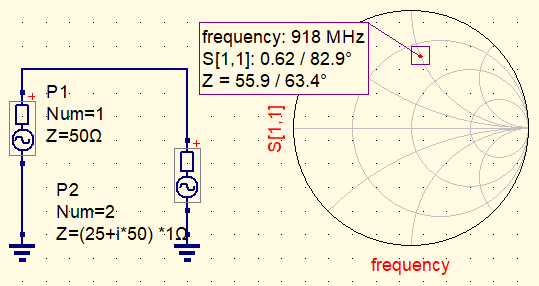
7. October 2025 at 3:24 in reply to: Frequency domain incorrect netlist interpretation/simulation. #9115Carsteen, to be clear: Port complex impedance is supported. But the SMITH tool does not support arbitrary reference impedance (Zo), only 50Ω. So it should be renormalized manually. And I have no idea how to do that, if there is any function for that.
Attachments:
6. October 2025 at 16:57 in reply to: Frequency domain incorrect netlist interpretation/simulation. #9114See the circuit – all the shunt network is the same node – zero impedance. It should not give different results regardless of connecting the middle point.
6. October 2025 at 16:52 in reply to: Frequency domain incorrect netlist interpretation/simulation. #9113Regardless of supported or not – the BUGREPORT is about different thing –
incorrect handling of the netlist
6. October 2025 at 16:51 in reply to: Frequency domain incorrect netlist interpretation/simulation. #9112Carsteen. For longer than 2 years it was told exactly contrary – it should support, though it is not well documented, since the latest QucksStudio.
I think there even was a discussion on this forum.
There are many badly documented things like Touchstone imedance conversion matrix…. which does not work correctly btw, while the devs claim it should do the thing.
6. October 2025 at 8:20 in reply to: Frequency domain incorrect netlist interpretation/simulation. #9110Version 5.8
P.S. a scale of the plot may be logically implemented by adding a unit suffic to the Start/Stop/Step values
I have a question about some older bugs and limitations, were they fized or not?
1. It was not possible using complex power source impedance. Even when defined with “i”, only its real part was treated. Can we use complex sources(loads) now? It is essential when modelling real devices, like antenna frontends. (have you ever seen an antenna with wideband purely real impedance? I guess, only in 1st course textbook)
2. Since it is often essential matching to real measured load/source, there was a feature in [S-parameters] block, called “ComplexZ”. Ideally, it should have converted the simulated fixed-Z port into the measured frequency dependent complex impedance port reprezentation, with the VNA-acquired data.
But it was not working. I mean, people, including developers believed it worked, but it was producing garbage data. I checked it with Agilent-ADS, and real life components many times. In V.4 it was crippled.
Was it fixed in V.5?
7. May 2024 at 7:15 in reply to: Incorrect sourceimpedance when using S1P block with measured impeedance. #8382There obviously was a comma, which I separated for your ease, and forgot to clear “but”, but lets not discuss stylistics, because everything is told in the next sentence.
The floating circuit is floating in the air and does not nave any ground potential explicitly defined, or has a reactance in the return path in other words. I think, that is obvious, since you cannot simulate truly floating potential (like unconnected pins) without introducing some stochastic environment model.
The Ground potential is defined at the other side of the circuit, at the port-2.
But as you see, I tried simulating with fixed GND potentials at both ports, it did not change anything.
>Mind, that you acquired a s1p file, but are using a 2-port-symbol
That is a feature of S1P-block. Follow the refrence. With “ComplexZ0″ function it converts the fixed impedance port, into the measured S1P impedance. <span style=”text-decoration: underline;”>I.e. it should, but it does not because of some bug.</span>
> That is seemingly needed, if you have complex port impedances.
That is exactly what I have – complex frequency dependant port jmpedances. Technically, CST and ADS solve this problem without efforts. And “ComplexZ0” function should do the same.
-
This reply was modified 1 year, 9 months ago by
Andy_JP.
-
AuthorPosts