Forum Replies Created
-
AuthorPosts
-
Indeed. Didn’t see that 🙂
There are textbook formulas for that. you could add “parameter sweeps” for W and h and use normal formula blocks to calculate Z0. Then you should be able to plot with cartesian etc. Maybe you have to add a little rf simulation to satisfy Qucs
Hi DrZrD,
What do you mean by “SCH assignments”?
Could you explain the problem in other words, please?
11. October 2025 at 0:30 in reply to: Frequency domain incorrect netlist interpretation/simulation. #9125A simplified example:
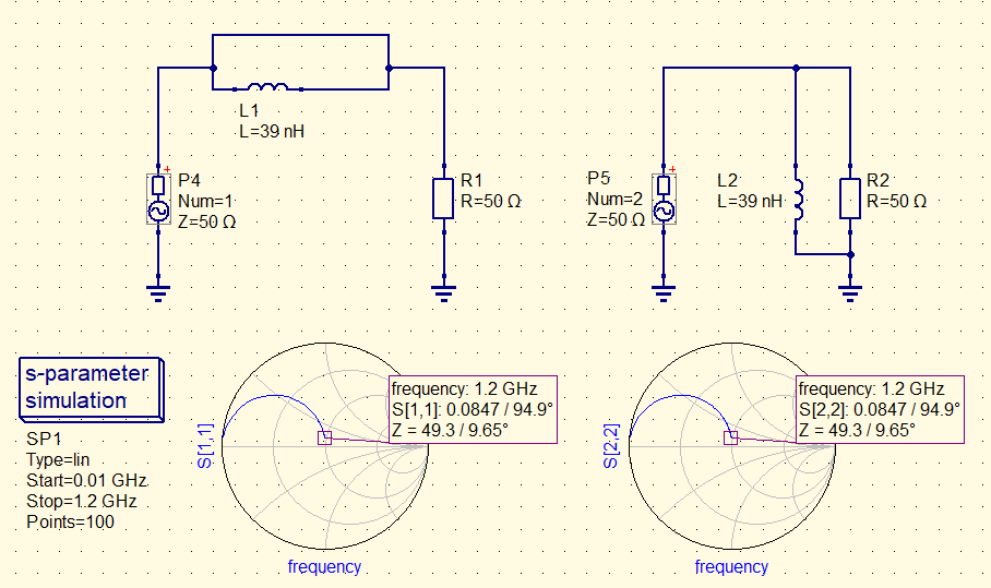
The inductor on the left is interpreted as being parallel to R1
The netlist generated for the left circuit alone seems ok:
R:R1 gnd _net0 “50 Ω” “26.85” “european” “SMD0603”
L:L1 _net0 _net0 “39 nH” “0” “” “inductor_1mH”
.SP:SP1 “lin” “0.01 GHz” “1.2 GHz” “100” “no” “1” “2” “none”
Pac:P4 _net0 gnd “1” “50 Ω” “0 dBm” “1 GHz” “26.85” “con_2”I don’t like that.
Please post the .sch file.
Hello Dieter,
I can image being this person. I designed filters for MRI coils so far.
You can check my linkedIn: https://www.linkedin.com/in/carsten-k%C3%B6gler-584a2387/
You can also contact me there.
Best wishes
Carsten
6. October 2025 at 14:55 in reply to: Frequency domain incorrect netlist interpretation/simulation. #9111usimmics does not support complex source impedances yet. Does the effect disappear if the source impedances are real?
22. September 2025 at 9:53 in reply to: Assigning the power port (usually real 50 ohms) to a S parameter file, #9095> I need to assign the power port for wideband impedance matching to a S parameter file.
You want to export the resulting s-parameters to a touchstone file?
22. September 2025 at 9:47 in reply to: ee_Formulas and mw_Formulas: special characters not displayable #9094QucsStudio/uSimmics has not been developed for Linux. There are glitches when using it via Wine. Michael usually does not provide support for these issues.
Hi Mike,
Voltage/current probes only provide a measurement if an AC simulation block is present. To achieve this, you need to deactivate the S parameter simulation block. The original Qucs could have both simulation blocks activated. Perhaps that’s why it’s in the documentation.
Best
Carsten
Components -> Paintings -> Text
17. February 2025 at 10:37 in reply to: Several mutual inductors model, cant modify the coupling factors #8897Can confirm it.
BTW: Models “Two mutual inductors” and “Three mutual inductors” works fine.
Hi,
In the “Equation defined component in frequency domain”, the variable ‘freq’ is defined. So you can do things like this (equals a 10nH inductor)

But ‘freq’ is not defined in equation blocks.
13. December 2024 at 13:04 in reply to: S-parameter simulation AC power source always at +10 dBm #8879According to F1 help:
dBm(x,Z)
convert voltage across impedance Z into (active) power in dBm (parameter Z is optional, default 50)dBm() should be applied to voltages. S-parameters are dimensionless voltage ratios.
S21 is 1 for such a circuit. An impedance of 50 Ohm and 1 V_peak would dissipate 1/100 W of power. Equals +10dBm
11. December 2024 at 13:33 in reply to: S-parameter simulation AC power source always at +10 dBm #8876S-Parameters are linear, so the power level has no influence. I suspect, a power level is not even defined / needed by the solver.
How did you measure the power? The voltage and current probes do not work with a S-Paramter-Block active
-
AuthorPosts